نمونه سوالات آزمون CCNA Routing & Switching 200-120
Topic 7, Troubleshooting
QUESTION NO: 221
Refer to the exhibit:

Hosts in network 192.168.2.0 are unable to reach hosts in network 192.168.3.0. Based on the output from RouterA, what are two possible reasons for the failure? (Choose two.)
A. The cable that is connected to S0/0 on RouterA is faulty.
B. Interface S0/0 on RouterB is administratively down.
C. Interface S0/0 on RouterA is configured with an incorrect subnet mask.
D. The IP address that is configured on S0/0 of RouterB is not in the correct subnet.
E. Interface S0/0 on RouterA is not receiving a clock signal from the CSU/DSU.
F. The encapsulation that is configured on S0/0 of RouterB does not match the encapsulation that is configured on S0/0 of RouterA.
Answer: E,F
Explanation:
From the output we can see that there is a problem with the Serial 0/0 interface. It is enabled, but the line protocol is down. The could be a result of mismatched encapsulation or the interface not receiving a clock signal from the CSU/DSU.
QUESTION NO: 222
Refer to the exhibit.
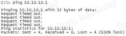
An administrator pings the default gateway at 10.10.10.1 and sees the output as shown. At which OSI layer is the problem?
A. data link layer
B. application layer
C. access layer
D. session layer
E. network layer
Answer: E
Explanation:
The command ping uses ICMP protocol, which is a network layer protocol used to propagate control message between host and router. The command ping is often used to verify the network connectivity, so it works at the network layer.
QUESTION NO: 223
Refer to the exhibit.
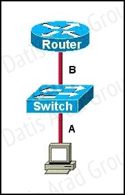
The two connected ports on the switch are not turning orange or green. What would be the most effective steps to troubleshoot this physical layer problem? (Choose three.)
A. Ensure that the Ethernet encapsulations match on the interconnected router and switch ports.
B. Ensure that cables A and B are straight-through cables.
C. Ensure cable A is plugged into a trunk port.
D. Ensure the switch has power.
E. Reboot all of the devices.
F. Reseat all cables.
Answer: B,D,F
Explanation:
The ports on the switch are not up indicating it is a layer 1 (physical) problem so we should check cable type, power and how they are plugged in.
QUESTION NO: 224
Refer to the exhibit.
 The network shown in the diagram is experiencing connectivity problems. Which of the following will correct the problems? (Choose two.)
A. Configure the gateway on Host A as 10.1.1.1.
B. Configure the gateway on Host B as 10.1.2.254.
C. Configure the IP address of Host A as 10.1.2.2.
D. Configure the IP address of Host B as 10.1.2.2.
E. Configure the masks on both hosts to be 255.255.255.224.
F. Configure the masks on both hosts to be 255.255.255.240.
Answer: B,D
Explanation:
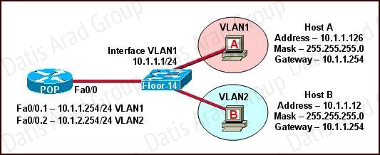
The switch 1 is configured with two VLANs: VLAN1 and VLAN2.
The IP information of member Host A in VLAN1 is as follows:
Address : 10.1.1.126
Mask : 255.255.255.0
Gateway : 10.1.1.254
The IP information of member Host B in VLAN2 is as follows:
Address : 10.1.1.12
Mask : 255.255.255.0
Gateway : 10.1.1.254
The configuration of sub-interface on router 2 is as follows:
Fa0/0.1 -- 10.1.1.254/24 VLAN1
Fa0/0.2 -- 10.1.2.254/24 VLAN2
It is obvious that the configurations of the gateways of members in VLAN2 and the associated network segments are wrong. The layer3 addressing information of Host B should be modified asfollows:
Address : 10.1.2.X
Mask : 255.255.255.0
QUESTION NO: 225
Refer to the exhibit.
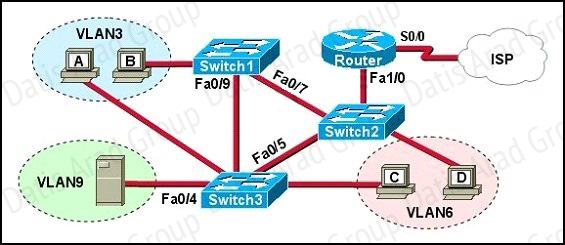
A problem with network connectivity has been observed. It is suspected that the cable connected to switch port Fa0/9 on Switch1 is disconnected. What would be an effect of this cable being disconnected?
A. Host B would not be able to access the server in VLAN9 until the cable is reconnected.
B. Communication between VLAN3 and the other VLANs would be disabled.
C. The transfer of files from Host B to the server in VLAN9 would be significantly slower.
D. For less than a minute, Host B would not be able to access the server in VLAN9. Then normal network function would resume.
Answer: D
Explanation:
Spanning-Tree Protocol (STP) is a Layer 2 protocol that utilizes a special-purpose algorithm to discover physical loops in a network and effect a logical loop-free topology. STP creates a loopfree tree structure consisting of leaves and branches that span the entire Layer 2 network. The actual mechanics of how bridges communicate and how the STP algorithm works will be discussed at length in the following topics. Note that the terms bridge and switch are used interchangeably when discussing STP. In addition, unless otherwise indicated, connections between switches are assumed to be trunks.
QUESTION NO: 226
Refer to the exhibit.
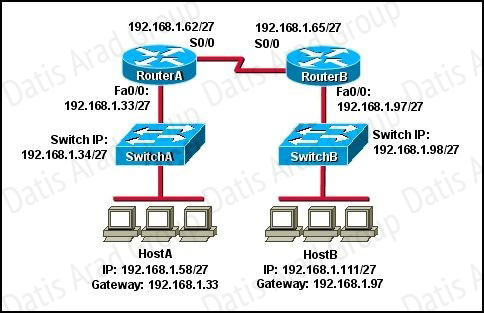 HostA cannot ping HostB. Assuming routing is properly configured, what is the cause of this problem?
A. HostA is not on the same subnet as its default gateway.
B. The address of SwitchA is a subnet address.
C. The Fa0/0 interface on RouterA is on a subnet that can't be used.
D. The serial interfaces of the routers are not on the same subnet.
E. The Fa0/0 interface on RouterB is using a broadcast address.
Answer: D
Explanation:
Now let’s find out the range of the networks on serial link:
For the network 192.168.1.62/27:
Increment: 32
Network address: 192.168.1.32
Broadcast address: 192.168.1.63
For the network 192.168.1.65/27:
Increment: 32
Network address: 192.168.1.64
Broadcast address: 192.168.1.95
-> These two IP addresses don’t belong to the same network and they can’t see each other
QUESTION NO: 227
Which router IOS commands can be used to troubleshoot LAN connectivity problems? (Choose three.)
A. ping
B. tracert
C. ipconfig
D. show ip route
E. winipcfg
F. show interfaces
Answer: A,D,F
Explanation:
Ping, show ip route, and show interfaces are all valid troubleshooting IOS commands. Tracert, ipconfig, and winipcfg are PC commands, not IOS.
QUESTION NO: 228
A network administrator is troubleshooting the OSPF configuration of routers R1 and R2. The routers cannot establish an adjacency relationship on their common Ethernet link.
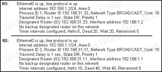
The graphic shows the output of the show ip ospf interface e0 command for routers R1 and R2. Based on the information in the graphic, what is the cause of this problem?
A. The OSPF area is not configured properly.
B. The priority on R1 should be set higher.
C. The cost on R1 should be set higher.
D. The hello and dead timers are not configured properly.
E. A backup designated router needs to be added to the network.
F. The OSPF process ID numbers must match.
Answer: D
Explanation:
In OSPF, the hello and dead intervals must match and here we can see the hello interval is set to 5 on R1 and 10 on R2. The dead interval is also set to 20 on R1 but it is 40 on R2.
QUESTION NO: 229
In which circumstance are multiple copies of the same unicast frame likely to be transmitted in a switched LAN?
A. during high traffic periods
B. after broken links are re-established
C. when upper-layer protocols require high reliability
D. in an improperly implemented redundant topology
E. when a dual ring topology is in use
Answer: D
Explanation:
If we connect two switches via 2 or more links and do not enable STP on these switches then a loop (which creates multiple copies of the same unicast frame) will occur. It is an example of an improperly implemented redundant topology.
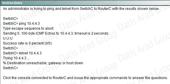
QUESTION NO: 230


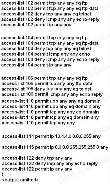
Which will fix the issue and allow ONLY ping to work while keeping telnet disabled?
A. Correctly assign an IP address to interface fa0/1.
B. Change the ip access-group command on fa0/0 from "in* to "out.
C. Remove access-group 106 in from interface fa0/0 and add access-group 115 in.
D. Remove access-group 102 out from interface s0/0/0 and add access-group 114 in
E. Remove access-group 106 in from interface fa0/0 and add access-group 104 in.
Answer: E
Explanation:
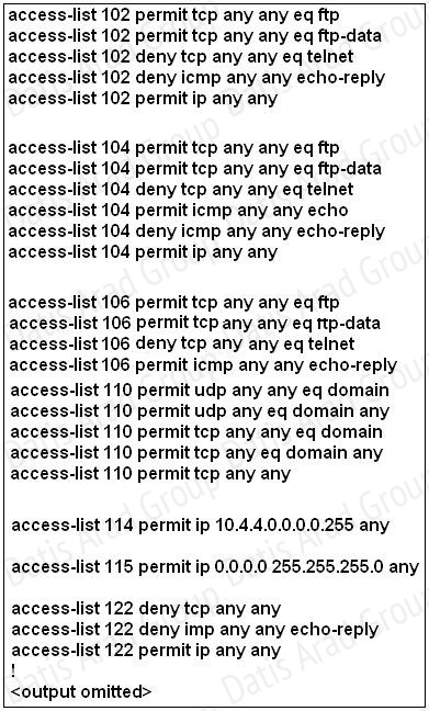
Let’s have a look at the access list 104:
 The question does not ask about ftp traffic so we don’t care about the two first lines. The 3rd line denies all telnet traffic and the 4th line allows icmp traffic to be sent (ping). Remember that the access list 104 is applied on the inbound direction so the 5th line “access-list 104 deny icmp any any echo-reply” will not affect our icmp traffic because the “echo-reply” message will be sent over the outbound direction.
QUESTION NO: 231
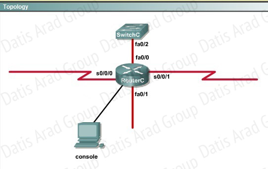
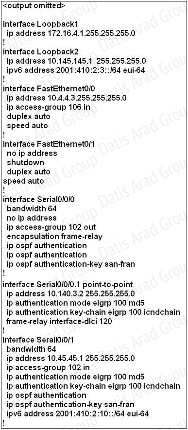

What would be the effect of issuing the command ip access-group 114 in to the fa0/0 interface?
A. Attempts to telnet to the router would fail.
B. It would allow all traffic from the 10.4.4.0 network.
C. IP traffic would be passed through the interface but TCP and UDP traffic would not.
D. Routing protocol updates for the 10.4.4.0 network would not be accepted from the fa0/0 interface.
Answer: B
Explanation:
From the output of access-list 114: access-list 114 permit ip 10.4.4.0 0.0.0.255 any we can easily understand that this access list allows all traffic (ip) from 10.4.4.0/24 network.
QUESTION NO: 232
Refer to the exhibit.
What would be the effect of Issuing the command ip access-group 115 in on the s0/0/1 interface?
A. No host could connect to RouterC through s0/0/1.
B. Telnet and ping would work but routing updates would fail.
C. FTP, FTP-DATA, echo, and www would work but telnet would fail.
D. Only traffic from the 10.4.4.0 network would pass through the interface.
Answer: A
Explanation:
First let’s see what was configured on interface S0/0/1:
QUESTION NO: 233 Scenario

Answer:
On the MGT Router:
Config t
Router eigrp 12
Network 192.168.77.0
QUESTION NO: 234 Scenario

A network associate is configuring a router for the weaver company to provide internet access. The ISP has provided the company six public IP addresses of 198.18.184.105 198.18.184.110. The company has 14 hosts that need to access the internet simultaneously. The hosts in the company LAN have been assigned private space addresses in the range of 192.168.100.17 – 192.168.100.30.
Answer:
The company has 14 hosts that need to access the internet simultaneously but we just have 6 public IP addresses from 198.18.184.105 to 198.18.184.110/29.
Therefore we have to use NAT overload (or PAT).
Double click on the Weaver router to open it.
Router>enable
Router#configure terminal
First you should change the router's name to Weaver
Router(config)#hostname Weaver
Create a NAT pool of global addresses to be allocated with their netmask.
Weaver(config)#ip nat pool mypool 198.18.184.105 198.18.184.110 netmask 255.255.255.248
Create a standard access control list that permits the addresses that are to be translated
Weaver(config)#access-list 1 permit 192.168.100.16 0.0.0.15
Establish dynamic source translation, specifying the access list that was defined in the prior step
Weaver(config)#ip nat inside source list 1 pool mypool overload
This command translates all source addresses that pass access list 1, which means a source address from 192.168.100.17 to 192.168.100.30, into an address from the pool named mypool (the pool contains addresses from 198.18.184.105 to 198.18.184.110)
Overload keyword allows to map multiple IP addresses to a single registered IP address (many-to-one) by using different ports
The question said that appropriate interfaces have been configured for NAT inside and NAT outside statements.
This is how to configure the NAT inside and NAT outside, just for your understanding:
Weaver(config)#interface fa0/0
Weaver(config-if)#ip nat inside
Weaver(config-if)#exit
Weaver(config)#interface s0/0
Weaver(config-if)#ip nat outside
Weaver(config-if)#end
Finally, we should save all your work with the following command:
Weaver#copy running-config startup-config
Check your configuration by going to "Host for testing" and type:
C :\>ping 192.0.2.114
The ping should work well and you will be replied from 192.0.2.114
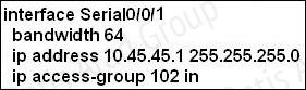
QUESTION NO: 235 Scenario
Central Florida Widgets recently installed a new router in their office. Complete the network installation by performing the initial router configurations and configuring R1PV2 routing using the router command line interface (CLI) on the RC.
Configure the router per the following requirements:
Name of the router is R2
Enable. secret password is cisco
The password to access user EXEC mode using the console is cisco2
The password to allow telnet access to the router is cisco3
IPV4 addresses mast be configured as follows:
Ethernet network 209.165.201.0/27 - router has fourth assignable host address in subnet
Serial network is 192.0.2.176/28 - router has last assignable host address in the subnet.
Interfaces should be enabled.
Router protocol is RIPV2
Attention:
In practical examinations, please note the following, the actual information will prevail.
1. Name or the router is xxx
2. EnablE. secret password is xxx
3. Password In access user EXEC mode using the console is xxx
4. The password to allow telnet access to the router is xxx
5. IP information
Answer:
Answer: Router>enable
Router#config terminal
Router(config)#hostname R2
R2(config)#enable secret Cisco 1
R2(config)#line console 0
R2(config-line)#password Cisco 2
R2(config-line)#exit
R2(config)#line vty 0 4
R2(config-line)#password Cisco 3
R2(config-line)#login
R2(config-line)#exit
R2(config)#interface faO/0
R2(config-if)#ip address 209.165.201.4 255.255.255.224
R2(config)#interface s0/0/0
R2(config-if)#ip address 192.0.2.190 255.255.255.240
R2(config-if)#no shutdown
R2(config-if)#exit
R2(config)#router rip
R2(config-router)#version 2
R2(config-router)#network 209.165.201.0
R2(config-router)#network 192.0.2.176
R2(config-router)#end
R2#copy run start
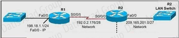
QUESTION NO: 236 Scenario
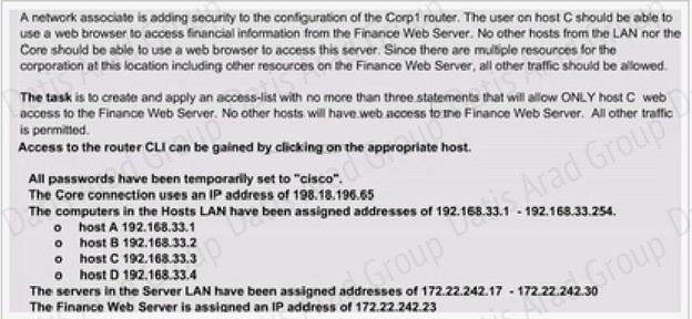
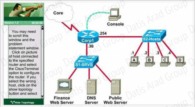
Answer:
Select the console on Corp1 router
Configuring ACL:
Corp1>enable
Corp1#configure terminal
comment: To permit only Host C (192.168.33.3){source addr} to access finance server address (172.22.242.23) {destination addr} on port number 80 (web)
Corp1(config)#access-list 100 permit tcp host 192.168.33.3 host 172.22.242.23 eq 80
comment: To deny any source to access finance server address (172.22.242.23) {destination addr} on port number 80 (web)
Corp1(config)#access-list 100 deny tcp any host 172.22.242.23 eq 80
comment: To permit ip protocol from any source to access any destination because of the implicit deny any any statement at the end of ACL.
Corp1(config)#access-list 100 permit ip any any
Applying the ACL on the Interface:
comment: Check show ip interface brief command to identify the interface type and number by checking the IP address configured.
Corp1(config)#interface fa 0/1
If the ip address configured already is incorrect as well as the subnet mask. This should be corrected in order ACL to work.
Type this commands at interface mode :
no ip address 192.x.x.x 255.x.x.x (removes incorrect configured ipaddress and subnet mask)
Configure Correct IP Address and subnet mask :
ip address 172.22.242.30 255.255.255.240 ( range of address specified going to server is given as 172.22.242.17 - 172.22.242.30 )
comment: Place the ACL to check for packets going outside the interface towards the finance web server.
Corp1(config-if)#ip access-group 100 out
Corp1(config-if)#end
Important: To save your running config to startup before exit.
Corp1#copy running-config startup-config
Verifying the Configuration :
Step1: show ip interface brief command identifies the interface on which to apply access list.
Step2: Click on each host A,B,C & D . Host opens a web browser page , Select address box of the web browser and type the ip address of finance web server(172.22.242.23) to test whether it permits /deny access to the finance web Server .
Step 3: Only Host C (192.168.33.3) has access to the server . If the other host can also access then maybe something went wrong in your configuration . check whether you configured correctly and in order.
Step 4: If only Host C (192.168.33.3) can access the Finance Web Server you can click on NEXT button to successfully submit the ACL SIM.
QUESTION NO: 237 Scenario

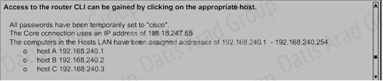
Answer:
Corp1(config)# access-list 128 permit tcp host 192.168.240.1 host 172.22.141.26 eq www
Corp1(config)# access-list 128 deny tcp any host 172.22.141.26 eq www
Corp1(config)# access-list 128 permit ip any any
Corp1(config)#int fa0/1
Corp1(config-if)#ip access-group 128 out
Corp1(config-if)#end
Corp1#copy run startup-config
QUESTION NO: 238 Scenario


Answer:
Corp1#configure terminal
Corp1(config)#access-list 100 permit tcp host 192.168.33.3 host 172.22.242.23 eq 80
Corp1(config)#access-list 100 deny tcp 192.168.33.0 0.0.0.255 host 172.22.242.23 eq 80
Corp1(config)#access-list 100 permit ip any any
Corp1(config)#interface fa 0/1 sh ip int brief
Corp1(config-if)#ip access-group 100 out
Corp1(config-if)#end
Corp1#copy running-config startup-config
Topic 8, WAN Technologies
QUESTION NO: 239
The output of the show frame-relay pvc command shows "PVC STATUS = INACTIVE". What does this mean?
A. The PVC is configured correctly and is operating normally, but no data packets have been detected for more than five minutes.
B. The PVC is configured correctly, is operating normally, and is no longer actively seeking the address of the remote router.
C. The PVC is configured correctly, is operating normally, and is waiting for interesting traffic to trigger a call to the remote router.
D. The PVC is configured correctly on the local switch, but there is a problem on the remote end of the PVC.
E. The PVC is not configured on the local switch.
Answer: D
Explanation:
The PVC STATUS displays the status of the PVC. The DCE device creates and sends the report to the DTE devices. There are 4 statuses:
+ ACTIVE: the PVC is operational and can transmit data.
+ INACTIVE: the connection from the local router to the switch is working, but the connection to the remote router is not available.
+ DELETED: the PVC is not present and no LMI information is being received from the Frame Relay switch.
+ STATIC: the Local Management Interface (LMI) mechanism on the interface is disabled (by using the “no keepalive” command). This status is rarely seen so it is ignored in some books.
QUESTION NO: 240 Drag and Drop

Answer:

نمونه سوالات آزمونهای سیسکو
CCNA Routing & Switching - exam 200-120
CCNA Collaboration (CICD) - exam 210-060
CCNA Collaboration (CIVND) - exam 210-065
Implementing Cisco IP Routing - exam 300-101
Implementing Cisco IP Switched - exam 300-115
Troubleshooting Cisco Networks - exam 300-135
نمونه سوالات آزمونهای مایکروسافت
Configuring Windows Server 2012 - exam 70-410
Administering Windows Server 2012 - exam 70-411
Advanced Windows Server 2012 - exam 70-412
Designing a Server Infrastructure - exam 70-413
Implementing Server Infrastructure - exam 70-414
اولین کتاب CCNA Voice به زبان فارسی منتشر شد. برای اطلاعات بیشتر و دریافت بخشی از کتاب, بر روی لینک کلیک کنید.