نمونه سوالات آزمون
Implementing Cisco IP Routing - exam 300-101
Topic 3, Layer 3 Technologies
QUESTION NO: 21
What is the default OSPF hello interval on a Frame Relay point-to-point network?
A. 10
B. 20
C. 30
D. 40
Answer: A
QUESTION NO: 22
A router with an interface that is configured with ipv6 address autoconfig also has a link-local address assigned. Which message is required to obtain a global unicast address when a router is present?
A. DHCPv6 request
B. router-advertisement
C. neighbor-solicitation
D. redirect
Answer: B
Explanation:
Autoconfiguration is performed on multicast-enabled links only and begins when a multicastenabled interface is enabled (during system startup or manually). Nodes (both, hosts and routers) begin the process by generating a link-local address for the interface. It is formed by appending the interface identifier to well-known link-local prefix FE80 :: 0. The interface identifier replaces the right-most zeroes of the link-local prefix.Before the link-local address can be assigned to the interface, the node performs the Duplicate Address Detection mechanism to see if any other node is using the same link-local address on the link. It does this by sending a Neighbor Solicitation message with target address as the "tentative" address and destination address as the solicitednode multicast address corresponding to this tentative address. If a node responds with a Neighbor Advertisement message with tentative address as the target address, the address is a duplicate address and must not be used. Hence, manual configuration is required.Once the node verifies that its tentative address is unique on the link, it assigns that link-local address to the interface. At this stage, it has IP-connectivity to other neighbors on this link.The autoconfiguration on the routers stop at this stage, further tasks are performed only by the hosts. The routers will need manual configuration (or stateful configuration) to receive site-local or global addresses.The next phase involves obtaining Router Advertisements from routers if any routers are present on the link. If no routers are present, a stateful configuration is required. If routers are present, the Router Advertisements notify what sort of configurations the hosts need to do and the hosts receive a global unicast IPv6 address.
QUESTION NO: 23
An engineer has configured a router to use EUI-64, and was asked to document the IPv6 address of the router. The router has the following interface parameters:
mac address C601.420F.0007
subnet 2001:DB8:0:1::/64
Which IPv6 addresses should the engineer add to the documentation?
A. 2001:DB8:0:1:C601:42FF:FE0F:7
B. 2001:DB8:0:1:FFFF:C601:420F:7
C. 2001:DB8:0:1:FE80:C601:420F:7
D. 2001:DB8:0:1:C601:42FE:800F:7
Answer: A
Explanation:
Extended Unique Identifier (EUI), as per RFC2373, allows a host to assign iteslf a unique 64-Bit IP Version 6 interface identifier (EUI-64). This feature is a key benefit over IPv4 as it eliminates the need of manual configuration or DHCP as in the world of IPv4. The IPv6 EUI-64 format address is obtained through the 48-bit MAC address. The Mac address is first separated into two 24-bits, with one being OUI (Organizationally Unique Identifier) and the other being NIC specific. The 16-bit 0xFFFE is then inserted between these two 24-bits to for the 64-bit EUI address. IEEE has chosen FFFE as a reserved value which can only appear in EUI-64 generated from the EUI-48 MAC address.
Here is an example showing how the Mac Address is used to generate EUI.
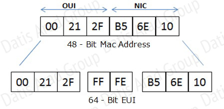
Next, the seventh bit from the left, or the universal/local (U/L) bit, needs to be inverted. This bit identifies whether this interface identifier is universally or locally administered. If 0, the address is locally administered and if 1, the address is globally unique. It is worth noticing that in the OUI portion, the globally unique addresses assigned by the IEEE has always been set to 0 whereas the locally created addresses has 1 configured. Therefore, when the bit is inverted, it maintains its original scope (global unique address is still global unique and vice versa). The reason for inverting can be found in RFC4291 section 2.5.1.
QUESTION NO: 24
For security purposes, an IPv6 traffic filter was configured under various interfaces on the local router. However, shortly after implementing the traffic filter, OSPFv3 neighbor adjacencies were lost. What caused this issue?
A. The traffic filter is blocking all ICMPv6 traffic.
B. The global anycast address must be added to the traffic filter to allow OSPFv3 to work properly.
C. The link-local addresses that were used by OSPFv3 were explicitly denied, which caused the neighbor relationships to fail.
D. IPv6 traffic filtering can be implemented only on SVIs.
Answer: C
Explanation:
OSPFv3 uses link-local IPv6 addresses for neighbor discovery and other features, so if any IPv6 traffic filters are implemented be sure to include the link local address so that it is permitted in the filter list.
QUESTION NO: 25
What is the purpose of the autonomous-system {autonomous-system-number} command?
A. It sets the EIGRP autonomous system number in a VRF.
B. It sets the BGP autonomous system number in a VRF.
C. It sets the global EIGRP autonomous system number.
D. It sets the global BGP autonomous system number.
Answer: A
Explanation:
To configure the autonomous-system number for an Enhanced Interior Gateway Routing Protocol (EIGRP) routing process to run within a VPN routing and forwarding (VRF) instance, use the autonomous-system command in address-family configuration mode. To remove the autonomous-system for an EIGRP routing process from within a VPN VRF instance, use the no form of this command.
autonomous-system autonomous-system-number
no autonomous-system autonomous-system-number
QUESTION NO: 26
Which type of traffic does DHCP snooping drop?
A. discover messages
B. DHCP messages where the source MAC and client MAC do not match
C. traffic from a trusted DHCP server to client
D. DHCP messages where the destination MAC and client MAC do not match
Answer: B
Explanation:
The switch validates DHCP packets received on the untrusted interfaces of VLANs with DHCP snooping enabled. The switch forwards the DHCP packet unless any of the following conditions occur (in which case the packet is dropped):
•
The switch receives a packet (such as a DHCPOFFER, DHCPACK, DHCPNAK, or DHCPLEASEQUERY packet) from a DHCP server outside the network or firewall.
•
The switch receives a packet on an untrusted interface, and the source MAC address and the DHCP client hardware address do not match. This check is performed only if the DHCP snooping MAC address verification option is turned on.
•
The switch receives a DHCPRELEASE or DHCPDECLINE message from an untrusted host with an entry in the DHCP snooping binding table, and the interface information in the binding table does not match the interface on which the message was received.
•
The switch receives a DHCP packet that includes a relay agent IP address that is not 0.0.0.0. To support trusted edge switches that are connected to untrusted aggregation-switch ports, you can enable the DHCP option-82 on untrusted port feature, which enables untrusted aggregationswitch ports to accept DHCP packets that include option-82 information. Configure the port on the edge switch that connects to the aggregation switch as a trusted port.
QUESTION NO: 27
Refer to the exhibit.
 Which command only announces the 1.2.3.0/24 network out of FastEthernet 0/0?
A. distribute list 1 out
B. distribute list 1 out FastEthernet0/0
C. distribute list 2 out
D. distribute list 2 out FastEthernet0/0
Answer: D
Explanation:
Access list 2 is more specific, allowing only 1.2.3.0/24, whereas access list 1 permits all 1.0.0.0/8 networks. This question also asks us to apply this distribute list only to the outbound direction of the fast Ethernet 0/0 interface, so the correct command is “distribute list 2 out FastEthernet0/0.”
QUESTION NO: 28
Which prefix is matched by the command ip prefix-list name permit 10.8.0.0/16 ge 24 le 24?
A. 10.9.1.0/24
B. 10.8.0.0/24
C. 10.8.0.0/16
D. 10.8.0.0/23
Answer: B
Explanation:
With prefix lists, the ge 24 term means greater than or equal to a /24 and the le 24 means less than or equal to /24, so only a /24 is both greater than or equal to 24 and less than or equal to 24. This translate to any prefix in the 10.8.x.0/24 network, where X is any value in the 0-255 range. Only the choice of 10.8.0.0.24 matches this.
QUESTION NO: 29
Router A and Router B are configured with IPv6 addressing and basic routing capabilities using OSPFv3. The networks that are advertised from Router A do not show up in Router B's routing table. After debugging IPv6 packets, the message "not a router" is found in the output. Why is the routing information not being learned by Router B?
A. OSPFv3 timers were adjusted for fast convergence.
B. The networks were not advertised properly under the OSPFv3 process.
C. An IPv6 traffic filter is blocking the networks from being learned via the Router B interface that is connected to Router A.
D. IPv6 unicast routing is not enabled on Router A or Router B.
Answer: D
Explanation:
QUESTION NO: 30
After you review the output of the command show ipv6 interface brief, you see that several IPv6 addresses have the 16-bit hexadecimal value of "FFFE" inserted into the address. Based on this information, what do you conclude about these IPv6 addresses?
A. IEEE EUI-64 was implemented when assigning IPv6 addresses on the device.
B. The addresses were misconfigured and will not function as intended.
C. IPv6 addresses containing "FFFE" indicate that the address is reserved for multicast.
D. The IPv6 universal/local flag (bit 7) was flipped.
E. IPv6 unicast forwarding was enabled, but IPv6 Cisco Express Forwarding was disabled.
Answer: A
Explanation:
Extended Unique Identifier (EUI), as per RFC2373, allows a host to assign iteslf a unique 64-Bit IP Version 6 interface identifier (EUI-64). This feature is a key benefit over IPv4 as it eliminates the need of manual configuration or DHCP as in the world of IPv4. The IPv6 EUI-64 format address is obtained through the 48-bit MAC address. The Mac address is first separated into two 24-bits, with one being OUI (Organizationally Unique Identifier) and the other being NIC specific. The 16-bit 0xFFFE is then inserted between these two 24-bits to for the 64-bit EUI address. IEEE has chosen FFFE as a reserved value which can only appear in EUI-64 generated from the an EUI-48 MAC address.
Here is an example showing how a the Mac Address is used to generate EUI.

Next, the seventh bit from the left, or the universal/local (U/L) bit, needs to be inverted. This bit identifies whether this interface identifier is universally or locally administered. If 0, the address is locally administered and if 1, the address is globally unique. It is worth noticing that in the OUI portion, the globally unique addresses assigned by the IEEE has always been set to 0 whereas the locally created addresses has 1 configured. Therefore, when the bit is inverted, it maintains its original scope (global unique address is still global unique and vice versa). The reason for inverting can be found in RFC4291 section 2.5.1.

Once the above is done, we have a fully functional EUI-64 format address.
QUESTION NO: 31
A packet capture log indicates that several router solicitation messages were sent from a local host on the IPv6 segment. What is the expected acknowledgment and its usage?
A. Router acknowledgment messages will be forwarded upstream, where the DHCP server will allocate addresses to the local host.
B. Routers on the IPv6 segment will respond with an advertisement that provides an external path from the local subnet, as well as certain data, such as prefix discovery.
C. Duplicate Address Detection will determine if any other local host is using the same IPv6 address for communication with the IPv6 routers on the segment.
D. All local host traffic will be redirected to the router with the lowest ICMPv6 signature, which is statically defined by the network administrator.
Answer: B
Explanation:
Router Advertisements (RA) are sent in response to router solicitation messages. Router solicitation messages, which have a value of 133 in the Type field of the ICMP packet header, are sent by hosts at system startup so that the host can immediately autoconfigure without needing to wait for the next scheduled RA message. Given that router solicitation messages are usually sent by hosts at system startup (the host does not have a configured unicast address), the source address in router solicitation messages is usually the unspecified IPv6 address (0:0:0:0:0:0:0:0). If the host has a configured unicast address, the unicast address of the interface sending the router solicitation message is used as the source address in the message. The destination address in router solicitation messages is the all-routers multicast address with a scope of the link. When an RA is sent in response to a router solicitation, the destination address in the RA message is the unicast address of the source of the router solicitation message.
RA messages typically include the following information:
•
One or more onlink IPv6 prefixes that nodes on the local link can use to automatically configure their IPv6 addresses
•
Lifetime information for each prefix included in the advertisement
•
Sets of flags that indicate the type of autoconfiguration (stateless or stateful) that can be completed
•
Default router information (whether the router sending the advertisement should be used as a default router and, if so, the amount of time (in seconds) the router should be used as a default router)
•
Additional information for hosts, such as the hop limit and MTU a host should use in packets that it originates
QUESTION NO: 32 Labrator
Route.com is a small IT corporation that is attempting to implement the network shown in the exhibit. Currently the implementation is partially completed. OSPF has been configured on routers Chicago and NewYork. The SO/O interface on Chicago and the SO/1 interface on NewYork are in Area 0. The loopbackO interface on NewYork is in Area 1. However, they cannot ping from the serial interface of the Seattle router to the loopback interface of the NewYork router. You have been asked to complete the implementation to allow this ping.
ROUTE.com's corporate implementation guidelines require:
• The OSPF process ID for all routers must be 10.
• The routing protocol for each interface must be enabled under the routing process.
• The routing protocol must be enabled for each interface using the most specific wildcard mask
possible.
•The serial link between Seattle and Chicago must be in OSPF area 21.
Network Information
Seattle
S0/0 192.168.16.5/30 - Link between Seattle and Chicago
Secret Password: cisco
Chicago
S0/0 192.168.54.9/30 - Link between Chicago and NewYork
S0/1 192.168.16.6/30 - Link between Seattle and Chicago Secre
Password: cisco
NewYork
S0/1 192.168.54.10/30 - Link between Chicago and NewYork
Loopback0 172.16.189.189
Secret Password: cisco
Answer:
Explanation:
Seattle’s S0/0 IP Address is 192.168.16.5/30. So, we need to find the network address and wildcard mask of 192.168.16.5/30 in order to configure the OSPF.
IP Address: 192.168.16.5 /30
Subnet Mask: 255.255.255.252
Here subtract 252 from 2565, 256-252 = 4, hence the subnets will increment by 4.
First, find the 4th octet of the Network Address:
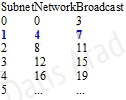
The 4th octet of IP address (192.168.16.5) belongs to subnet 1 (4 to 7).
Network Address: 192.168.16.4
Broadcast Address: 192.168.16.7
Lets find the wildcard mask of /30.
Subnet Mask: (Network Bits – 1’s, Host Bits – 0’s)
Lets find the wildcard mask of /30.
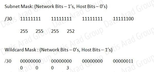
Now we configure OSPF using process ID 10 (note the process ID may change to something else in real exam).
Seattle>enable
Password:
Seattle#conf t
Seattle(config)#router ospf 10
Seattle(config-router)#network 192.168.16.4 0.0.0.3 area 21
One of the tasks states that area 21 should not receive any external or inter-area routes (except the default route).
Seattle(config-router)#area 21 stub
Seattle(config-router)#end
Seattle#copy run start
Chicago Configuration:
Chicago>enable
Password: cisco
Chicago#conf t
Chicago(config)#router ospf 10
We need to add Chicago’s S0/1 interface to Area 21
Chicago(config-router)#network 192.168.16.4 0.0.0.3 area 21
Again, area 21 should not receive any external or inter-area routes (except the default route). In order to accomplish this, we must stop LSA Type 5 if we don’t want to send external routes. And if we don’t want to send inter-area routes, we have to stop LSA Type 3 and Type 4. Therefore we want to configure area 21 as a totally stubby area.
Chicago(config-router)#area 21 stub no-summary
Chicago(config-router)#end
Chicago#copy run start
The other interface on the Chicago router is already configured correctly in this scenario, as well as the New York router so there is nothing that needs to be done on that router.
QUESTION NO: 33 Labrator
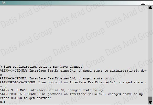
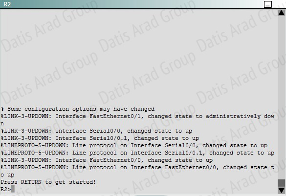
JS Industries has expanded their business with the addition of their first remote office. The remote office router (R3) was previously configured and all corporate subnets were reachable from R3. JS Industries is interested in using route summarization along with the EIGRP Stub Routing feature to increase network stability while reducing the memory usage and bandwidth utilization to R3. Another network professional was tasked with implementing this solution. However, in the process of configuring EIGRP stub routing connectivity with the remote network devices off of R3 has been lost.
Currently EIGRP is configured on all routers R2, R3, and R4 in the network. Your task is to identify and resolve the cause of connectivity failure with the remote office router R3. Once the issue has been resolved you should complete the task by configuring route summarization only to the remote office router R3. You have corrected the fault when pings from R2 to the R3 LAN interface are successful, and the R3 IP routing table only contains 2 10.0.0.0 subnets.

Explanation:
First we have to figure out why R3 and R4 can not communicate with each other. Use the show running-config command on router R3.
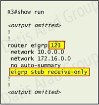
Notice that R3 is configured as a stub receive-only router. The receive-only keyword will restrict the router from sharing any of its routes with any other router in that EIGRP autonomous system. This keyword will also prevent any type of route from being sent. Therefore we will remove this command and replace it with the eigrp stub command:
R3# configure terminal
R3(config)# router eigrp 123
R3(config-router)# no eigrp stub receive-only
R3(config-router)# eigrp stub
R3(config-router)# end
Now R3 will send updates containing its connected and summary routes to other routers. Notice that the eigrp stub command equals to the eigrp stub connected summary because the connected and summary options are enabled by default. Next we will configure router R3 so that it has only 2 subnets of 10.0.0.0 network. Use the show ip route command on R3 to view its routing table:
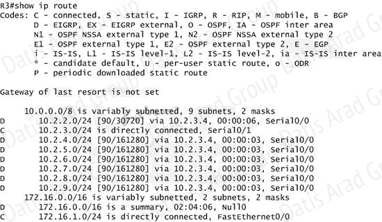
Because we want the routing table of R3 only have 2 subnets so we have to summary subnetworks at the interface which is connected with R3, the s0/0 interface of R4.
There is one interesting thing about the output of the show ip route shown above: the 10.2.3.0/24, which is a directly connected network of R3. We can’t get rid of it in the routing table no matter what technique we use to summary the networks. Therefore, to make the routing table of R3 has only 2 subnets we have to summary other subnets into one subnet.
In the output if we don’t see the summary line (like 10.0.0.0/8 is a summary…) then we should use the command ip summary-address eigrp 123 10.2.0.0 255.255.0.0 so that all the ping can work well.
In conclusion, we will use the ip summary-address eigrp 123 10.2.0.0 255.255.0.0 at the interface s0/0 of R4 to summary.
R4> enable R4# conf t
R4(config)# interface s0/0
R4(config-if)# ip summary-address eigrp 123 10.2.0.0 255.255.0.0
Now we jump back to R3 and use the show ip route command to verify the effect, the output is shown below:
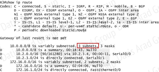
Note: Please notice that the IP addresses and the subnet masks in your real exam might be different so you might use different ones to solve this question. Just for your information, notice that if you use another network than 10.0.0.0/8 to summary, for example, if you use the command ip summary-address eigrp 123 10.2.0.0 255.255.0.0 you will leave a /16 network in the output of the show ip route command.
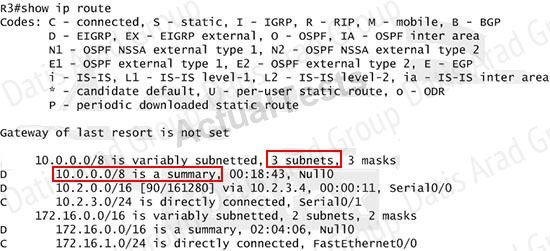
But in your real exam, if you don’t see the line "10.0.0.0/8 is a summary, Null0" then you can summarize using the network 10.2.0.0/16. This summarization is better because all the pings can work well.
Finally don’t forget to use the copy run start command on routers R3 and R4 to save the
configurations.
R3(config-if)# end
R3# copy run start
R4(config-if)# end
R4# copy run start
If the “copy run start” command doesn’t work then use “write memory.”
QUESTION NO: 34
ROUTE.com is a small IT corporation that has an existing enterprise network that is running IPv6 OSPFv3. Currently OSPF is configured on all routers. However, R4's loopback address (FEC0:4:4) cannot be seen in R1's IPv6 routing table. You are tasked with identifying the cause of this fault and implementing the needed corrective actions that uses OPSF features and does not change the current area assignments. You will know that you have corrected the fault when R4's loopback address (FEC0:4:4) can be seen in RTs IPv6 routing table.
Special Note: To gain the maximum number of points you must remove all incorrect or unneeded configuration statements related to this issue.

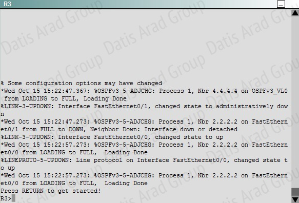
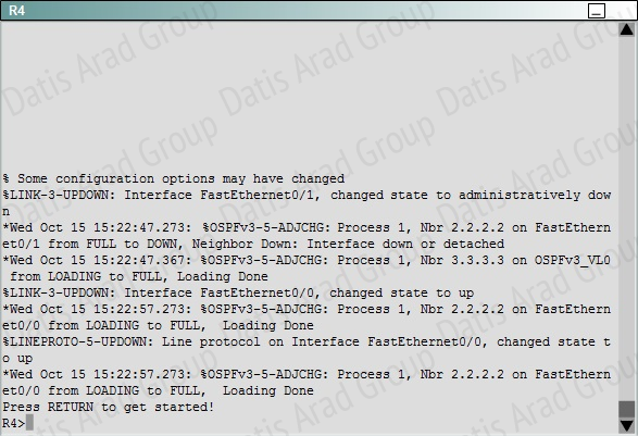
Explanation:
To troubleshoot the problem, first issue the show running-config on all of 4 routers. Pay more attention to the outputs of routers R2 and R3 The output of the "show running-config" command of R2:
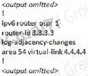
The output of the "show running-config" command of R3:
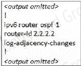
We knew that all areas in an Open Shortest Path First (OSPF) autonomous system must be physically connected to the backbone area (Area 0). In some cases, where this is not possible, we can use a virtual link to connect to the backbone through a non-backbone area. The area through which you configure the virtual link is known as a transit area. In this case, the area 11 will become the transit area. Therefore, routers R2 and R3 must be configured with the area <area id> virtuallink <neighbor router-id>command. + Configure virtual link on R2 (from the first output above, we learned that the OSPF process ID of R2 is 1):
R2>enable
R2#configure terminal
R2(config)#ipv6 router ospf 1
R2(config-rtr)#area 11 virtual-link 3.3.3.3
Save the configuration:
R2(config-rtr)#end
R2#copy running-config startup-config
(Notice that we have to use neighbor router-id 3.3.3.3, not R2's router-id 2.2.2.2) + Configure virtual link on R3 (from the second output above, we learned that the OSPF process ID of R3 is 1 and we have to disable the wrong configuration of "area 54 virtual-link 4.4.4.4"):
R3>enable
R3#configure terminal
R3(config)#ipv6 router ospf 1
R3(config-rtr)#no area 54 virtual-link 4.4.4.4
R3(config-rtr)#area 11 virtual-link 2.2.2.2
Save the configuration:
R3(config-rtr)#end
R3#copy running-config startup-config
You should check the configuration of R4, too. Make sure to remove the incorrect configuration statements to get the full points.
R4(config)#ipv6 router ospf 1
R4(config-router)#no area 54 virtual-link 3.3.3.3
R4(config-router)#end
After finishing the configuration doesn’t forget to ping between R1 and R4 to make sure they work.
Note. If you want to check the routing information, use the show ipv6 route command, not "show ip route".
QUESTION NO: 35
You are a network engineer with ROUTE.com, a small IT company. ROUTE.com has two connections to the Internet; one via a frame relay link and one via an EoMPLS link. IT policy requires that all outbound HTTP traffic use the frame relay link when it is available. All other traffic may use either link. No static or default routing is allowed.
Choose and configure the appropriate path selection feature to accomplish this task. You may use the Test Workstation to generate HTTP traffic to validate your solution.
Answer:
We need to configure policy based routing to send specific traffic along a path that is different from the best path in the routing table.
Here are the step by Step Solution for this:
1) First create the access list that catches the HTTP traffic:
R1(config)#access-list 101 permit tcp any any eq www
2) Configure the route map that sets the next hop address to be ISP1 and permits the rest of the traffic:
R1(config)#route-map pbr permit 10
R1(config-route-map)#match ip address 101
R1(config-route-map)#set ip next-hop 10.1.100.2
R1(config-route-map)#exit
R1(config)#route-map pbr permit 20
3) Apply the route-map on the interface to the server in the EIGRP Network:
R1(config-route-map)#exit
R1(config)#int fa0/1
R1(config-if)#ip policy route-map pbr
R1(config-if)#exit
R1(config)#exit
Explanation:
First you need to configure access list to HTTP traffic and then configure that access list. After that configure the route map and then apply it on the interface to the server in EIGRP network.
QUESTION NO: 36
You are a network engineer with ROUTE.com, a small IT company. They have recently merged two organizations and now need to merge their networks as shown in the topology exhibit. One network is using OSPF as its IGP and the other is using EIGRP as its IGP. R4 has been added to the existing OSPF network to provide the interconnect between the OSPF and EIGRP networks. Two links have been added that will provide redundancy.
The network requirements state that you must be able to ping and telnet from loopback 101 on R1 to the OPSF domain test address of 172.16.1.100. All traffic must use the shortest path that provides the greatest bandwidth. The redundant paths from the OSPF network to the EIGRP network must be available in case of a link failure. No static or default routing is allowed in either network.
A previous network engineer has started the merger implementation and has successfully assigned and verified all IP addressing and basic IGP routing. You have been tasked with completing the implementation and ensuring that the network requirements are met. You may not remove or change any of the configuration commands currently on any of the routers. You may add new commands or change default values.
Answer:
First we need to find out 5 parameters (Bandwidth, Delay, Reliability, Load, MTU) of the s0/0/0 interface (the interface of R2 connected to R4) for redistribution:
R2#show interface s0/0/0
Write down these 5 parameters, notice that we have to divide the Delay by 10 because the metric unit is in tens of microsecond. For example, we get Bandwidth=1544 Kbit, Delay=20000 us, Reliability=255, Load=1, MTU=1500 bytes then we would redistribute as follows:
R2#config terminal
R2(config)# router ospf 1
R2(config-router)# redistribute eigrp 100 metric-type 1 subnets
R2(config-router)#exit
R2(config-router)#router eigrp 100
R2(config-router)#redistribute ospf 1 metric 1544 2000 255 1 1500
Note: In fact, these parameters are just used for reference and we can use other parameters with no problem.
If the delay is 20000us then we need to divide it by 10, that is 20000 / 10 = 2000) For R3 we use the show interface fa0/0 to get 5 parameters too
R3#show interface fa0/0
For example we get Bandwidth=10000 Kbit, Delay=1000 us, Reliability=255, Load=1, MTU=1500 bytes
R3#config terminal
R3(config)#router ospf 1
R3(config-router)#redistribute eigrp 100 metric-type 1 subnets
R3(config)#exit
R3(config-router)#router eigrp 100
R3(config-router)#redistribute ospf 1 metric 10000 100 255 1 1500
Finally you should try to “show ip route” to see the 172.16.100.1 network (the network behind R4) in the routing table of R1 and make a ping from R1 to this network.
Note: If the link between R2 and R3 is FastEthernet link, we must put the command below under EIGRP process to make traffic from R1 to go through R3 (R1 -> R2 -> R3 -> R4), which is better than R1 -> R2 -> R4.
R2(config-router)# distance eigrp 90 105
This command sets the Administrative Distance of all EIGRP internal routes to 90 and all EIGRP external routes to 105, which is smaller than the Administrative Distance of OSPF (110) -> the link between R2 & R3 will be preferred to the serial link between R2 & R4.
Note: The actual OPSF and EIGRP process numbers may change in the actual exam so be sure to use the actual correct values, but the overall solution is the same.
QUESTION NO: 37
You have been asked to evaluate how EIGRP is functioning in a customer network.
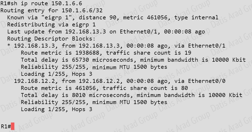
 Traffic from R1 to R61 s Loopback address is load shared between R1-R2-R4-R6 and R1-R3-R5- R6 paths. What is the ratio of traffic over each path?
A. 1:1
B. 1:5
C. 6:8
D. 19:80
Answer: D
Explanation:
First, find the IP address of the loopback0 interface on R6:
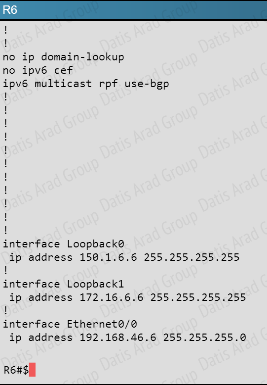
We see that it is 150.1.6.6, so we issue the “show ip route 150.1.6.6” command from R1 and see this:
Notice the “traffic share count” shows 19 for the first path, and 80 for the second path.
QUESTION NO: 38
You have been asked to evaluate how EIGRP is functioning in a customer network.
 What type of route filtering is occurring on R6
A. Distribute-list using an ACL
B. Distribute-list using a prefix-list
C. Distribute-list using a route-map
D. An ACL using a distance of 255
Answer: A
Explanation:
The configuration on R6 is as follows:
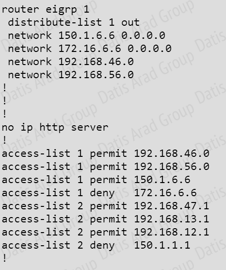
This is a standard distribute list using access list number 1.
QUESTION NO: 39
You have been asked to evaluate how EIGRP is functioning in a customer network.
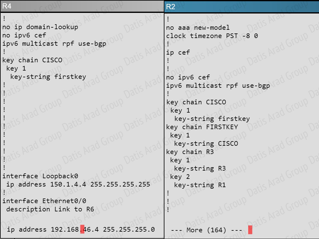
 Which key chain is being used for authentication of EIGRP adjacency between R4 and R2?
A. CISCO
B. EIGRP
C. key
D. MD5
Answer: A
Explanation:
R4 and R2 configs are as shown below:
Clearly we see the actual key chain is named CISCO.
QUESTION NO: 40
You have been asked to evaluate how EIGRP is functioning in a customer network.
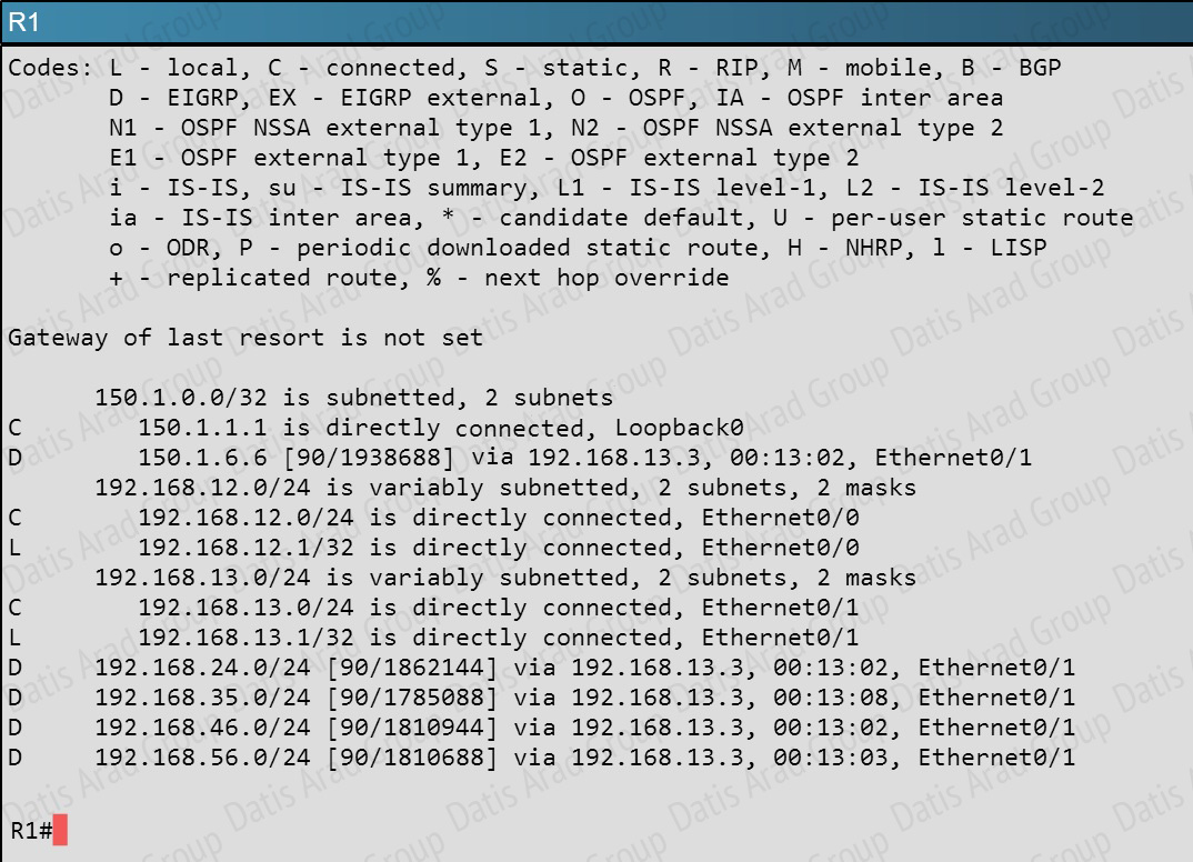
 What is the advertised distance for the 192.168.46.0 network on R1?
A. 333056
B. 1938688
C. 1810944
D. 307456
Answer: C
Explanation:
R1’s routing table is as follows
The numbers after the route specify the administrative distance of the route (90 for EIGRP) and the distance metric of that particular route, which is shows as 1810944 for the 192.168.46.0 route.

